The more I read about it the more I agree. It looks like a great way to pump water while being off the grid...
How a Hydraulic Ram Pump
works
The concept behind the ram idea is a "water hammer"
shock wave.Water has weight, so a
volume of water moving at a certain speed has momentum - it doesn't want to stop
immediately.If a car runs into a brick
wall the result is crumpled metal.If a
moving water flow in a pipe encounters a suddenly closed valve, a pressure
"spike" or increase suddenly appears due to all the water being stopped abruptly
(that's what water hammer is - the pressure spike).If you turn a valve off in your house
quickly, you may hear a small "thump" in the pipes.That's water hammer.
Here's how the hydraulic ram pump actually
works, step-by-step:
(2) At some point, water is moving so
quickly through the brass swing check "waste" valve (#4) that it grabs the swing
check's flapper, pulling it up and slamming it shut. The water in the pipe is
moving quickly and doesn't want to stop.All that water weight and momentum is stopped, though, by the valve
slamming shut.That makes a high
pressure spike (red arrows) at the closed valve. The high pressure spike forces
some water (blue arrows) through the spring check valve (#5 on the diagram) and
into the pressure chamber.This
increases the pressure in that chamber slightly. The pressure "spike" the pipe
has nowhere else to go, so it begins moving away from the waste valve and back
up the pipe (red arrows).It actually
generates a very small velocity *backward* in the pipe. (Click here to see an
actual image of an operating ram pump for this step. Note the drops of water
still falling to the ground in the image.)
(3) As the pressure wave or spike (red
arrows) moves back up the pipe, it creates a lower pressure situation (green
arrows) at the waste valve. The spring-loaded
check valve (#5) closes as the pressure drops, retaining the pressure in the
pressure chamber.
(4) At some point this pressure (green
arrows) becomes low enough that the flapper in the waste valve (#4) falls back
down, opening the waste valve again. (Click here to see an actual image of a ram pump
for this step.)
(5) Most of the water hammer high pressure shock wave (red arrows) will
release at the drive pipe inlet, which is open to the source water body. Some
small portion may travel back down the drive pipe, but in any case after
the shock wave has released, pressure begins to build again at the waste valve
(#4) simply due to the elevation of the source water above the ram, and water
begins to flow toward the hydraulic ram again. (6) Water begins to flow out of the waste
valve (#4), and the process starts over once again.
Steps 1 through 6 describe in layman's terms a complete cycle of a hydraulic
ram pump. Pressure wave theory will explain
the technical details of why a hydraulic ram pump works,but we only need to know it works.(One American company has been manufacturing
and selling hydraulic rams since the 1880’s).The ram pump will usually go through this cycle about once a second,
perhaps somewhat more quickly or more slowly depending on the installation. Each "pulse" or cycle pushes a little more
pressure into the pressure chamber.If
the outlet valve is left shut, the ram will build up to some maximum pressure
(called shutoff head on pumps) and stop working. The ram is quite inefficient.Usually 8 gallons of water must pass through
the waste valve for each 1 gallon of water pumped by the ram.That is acceptable for a creek or river
situation, but may not be a good option for a pond that does not have a good
spring flow.
PLANS
This information is provided as a service to those wanting to build their own
hydraulic ram pump. The data from our experiences with one of these home-made
hydraulic ram pumps is listed in Table 4 near the bottom of this document. The
typical cost of fittings for an 1-1/4" pump is currently $120.00 (U.S.A.)
regardless of whether galvanized or PVC fittings are used.
All connectors between the fittings are threaded pipe nipples - usually 2" in
length or shorter. This pump can be made from PVC fittings or galvanized steel.
In either case, it is recommended that the 4" diameter fittings be PVC fittings
to conserve weight.
Conversion Note: 1" (1 inch) = 2.54 cm; 1 PSI (pound/square
inch) = 6.895 KPa or 0.06895 bar; 1 gallon per minute = 3.78 liter per minute.
PR160 PVC pipe is PVC pipe rated at 160 psi pressure.
Click here to see a short
mpeg movie of an operating ram pump (Note - this is a 6.2 mb
movie clip. On slower systems (11 mbps, etc.), it will load "piece-meal"
the first time. Allow it to finish playing in this fashion, then press the play
button again to see it in full motion with no "buffering" stops. Dial-up users
may have to download the file to see it - simply right-click on the link, then
select "Save Target As..." to save it to your computer. Downloading may take
considerable time if you are on a slower dial-up system.)
Assembly Notes:
Pressure Chamber - A bicycle or "scooter tire" inner tube is
placed inside the pressure chamber (part 15) as an "air bladder" to prevent
water-logging or air-logging. Inflate the tube until it is "spongy" when
squeezed, then insert it in the chamber. It should not be inflated very tightly,
but have some "give" to it. Note that water will absorb air over time, so the
inner tube is used to help prevent much of this absorbtion. You may find it
necessary, however, to drain the ram pump occasionally to allow more air into
the chamber. (The University of Warwick design (link below, pages 12-13)
suggests the use of a "snifter" to allow air to be re-introduced to the ram
during operation. Their design, however, is substantially different from the
one offered here and provides a location (the branch of a tee) where the
addition of a snifter is logical. This design does not. Also, correctly sizing
the snifter valve (or hole as the case may be) can be problematical and may
allow the addition of too much air, resulting in air in the drive pipe and
ceasing of pumping operation. For these reasons we have elected not to include
one in this design.)
According to information provided by the University of Warwick (UK) ( http://www.eng.warwick.ac.uk/dtu/pubs/tr/lift/rptr12/tr12.pdf
, page 14), the pressure chamber should have a minimum volume of 20 times the
expected delivery flow per "cycle" of the pump, with 50 times the expected
delivery being a better selection. The chart below provides some recommended
minimum pressure chamber sizes based on 50 times the expected delivery flow per
"cycle." Note that larger pressure chambers will have not have any negative
impact on the pump performance (other than perhaps requiring a little more time
to initially start the pump). Some of the lengths indicated are quite
excessive, so you may prefer to use two or three pipes connected together in
parallel to provide the required pressure chamber volume. Well pump pressure
tanks will also work well - just make sure they have at least the minimum volume
required.
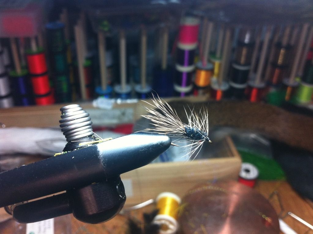
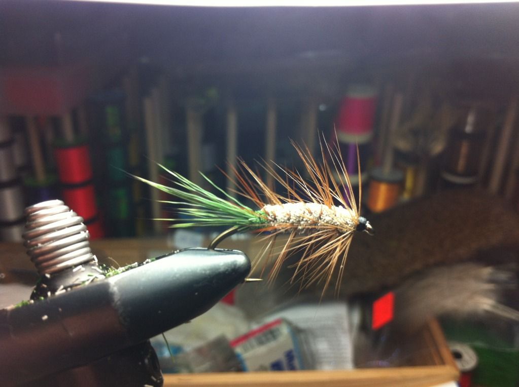
After the last couple months of tying nothing but large flashy flies for spring salmon it's time to switch gears and start thinking about brookies and brights ...
(Size 14 Mustad S82-3906B Signature Series)
Carter Bugs on Size 10 Mustad 9672 streamer hooks
Green Machines on Size 8 Mustad R50-94840 dry hooks
Big old hook is Size 3/0 Partridge CS10/1 Bartleet Traditional hooks (one of my main black salmon hooks)
These are rough but i'll get used to tying on smaller sizes soon enough!
Here's the 'boys escape to go fishing and be boys' weekend update with Ethan and his good buddy Nick! It all started a few weeks ago while we were up chasing kelts and Dad suggested we bring one of Ethan's pals along for a weekend of fishing. It was a great idea that we will definitely repeat in the near future! What's a trip to the Miramichi without a stop by a local flyshop for a few last minute supplies? (Ethan's been there dozens of times, he's just thrilled to have his pal along)
This is probably the least controversial thing the boys were up to while not out fishing.
Other activities included playing with matches, lighting fires, shooting tin cans with bb guns and whittling with hatchets... let's just say the boys were havin' a time :)
Even though the boys seemed to like the other activities more we managed to get a bit of fishing in. Dad managed to troll while running the tiller while I played the role of guide.
The boys/Dad caught a few trout and Dad managed a beautiful salmon. Nick hooked a small salmon but the acrobatics coupled with a reel malfunction broke it off. We'll get him next time Nick!
Fish on!
Miss Blackville:
Suppertime:
Good buddies:
Billy and I managed to sneak off to the river a few times while Dad looked after the tribe
(some pretty funny dialogue here)
Billy managed to get the job done with his new spey rod - he landed 2 salmon and was on cloud 9 Saturday! Way to go brother!
A few random pics
The Den:
Nick's fly:
To sum up, the boys had a great weekend and they're still talking about it at school! They're both eager to get back up and so are we!
I hope you like the pics, gents.
(this entry was originally made on my fishing log at nsflyguy.ca/smf)